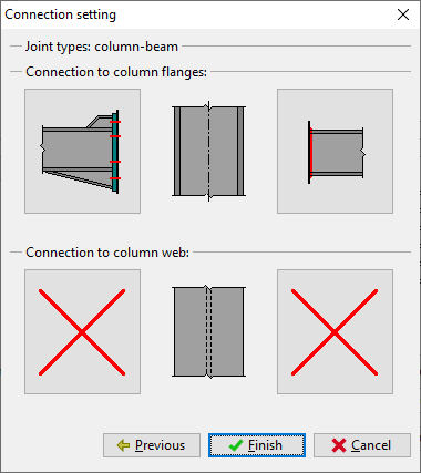
Beamtobeam connections Endplate type beam splice (platetoplate connection) Column bases Bolted base plate connection The types "beamtobeam" and "column bases" are limited to symmetric and asymmetric I beams (including the elements with variable height) and RHS sections, both for majoraxis bending configurations · Learn about the predefined types of structural connections There are 130 standard steel connections available in Revit You can load and use these connections in your model Beam end to end Apex haunch* Cranked beam to beam Double apex haunch Front plate splice* Moment column splice · Wf Beam Hss Column Connection For Flexible Moment Fmc Frame Structural Ering General Discussion Eng Risa structural ysis design beam column moment connection research future directions for capacity design of welded beam to column connections in steel seismic moment resisting frames welded joints of rolled and steel i sections seismic
Welded Joints Of Rolled And Welded Steel I Sections
I beam welded connection
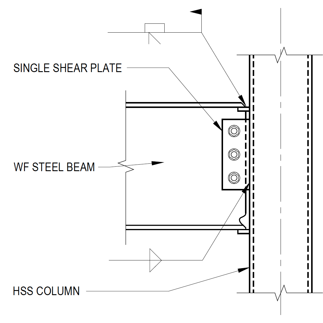
I beam welded connection-3 The directwelded connection, without seat angles represents the severest loading on the column at the connection However, the formulas developed by this investigation may be used for determining the need for, and the design of stiffeners when the beam Ranges are connected to the columns by buttwelded platesDirectly Welded Connection Example •Check beam and HSS failure modes, Transverse Plate connection (AISC table K12) •Local yielding of beam flange • ΦR n = 10/(B/t)F ytb f ≤ F yp tfbf • ΦR n = 584 k > 51 k OK 11 Directly Welded Connection Example •HSS shear yielding/punching
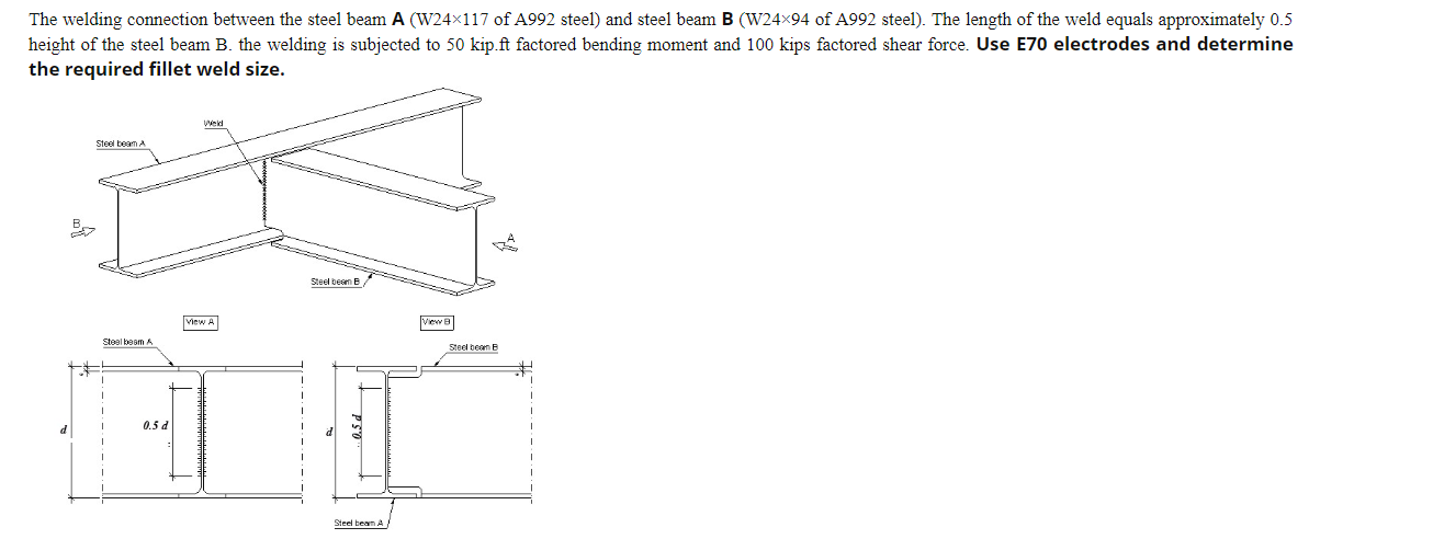


The Welding Connection Between The Steel Beam A Chegg Com
· Beams and columns are usually connected on site by bolting In the case of an RHS beam connection to an Isection column, a welded extended endplate to the RHS beam permits the use of a conventional bolted connection to the column flange or web (see Figure 633)However, welded connections are more flexible The holes used to bolt or pin pieces together during welding are usually drilled in the fabrication shop Beams are not usually welded directly to columns The procedure produces a rigid connection and results in severe bending that stresses the beam, which must be resisted by both the beam and the• Structural welding is a process whereby the parts to be connected are heated and fused with a molten filler metal • Upon cooling, the structural steel (parent metal) and weld or filler metal will act as one continuous part The filler metal is deposited from a special electrode A
Welded connections Bolted connections Pinned connections wwwVidyarthipluscom wwwVidyarthipluscom Page 2 10 Name the types of riveted connections?4 WELDED BEAM TO COLUMN MOMENT CONNECTION 41 Description of connection FIGURE 14 TYPICAL WELDED BEAM TO COLUMN MOMENT CONNECTION Structurally, the simplest rigid beamtocolumn moment connection is the welded moment connection, although it is a connection which does require precision in fabrication and fitupThe 610UB101 beam member shown in Figure 5(b) has six cleats welded to the web (three each side) intended to accept bolted secondary beams The total fabrication and weld time for this beam is nominally six hours The functionally equivalent beam shown in Figure 5(a) has holing for six bolted angle cleats (three each side) The total
Connection behavior can be presented by spring set model (Figure 2) Within Eurocode there are direct instructions on how to calculate stiffness coefficients for basic connection components with frontal plate, for welded connections and for connections with connecting angles at beam legs• For beams connected to the web of an unstiffened column or beam, the stiffness modification coefficient η is not relevant and these joints may be considered as hinges, see Gomes, Jaspart, 1994 and Gomes et al, 1994, for simplicity • For a continuous beam connected on both sides of the column web, see Figure 65a, theMany of our Beam Clamp solutions require a very precise look at loadings and beam configurations FastFit is a preengineered "all purpose" Ibeam connection solution that can be used to connect many different beams of varying sizes and angles If


Steel Beam Reduced Size Welded Splice Connection Detail Steel Beams Beams Weld
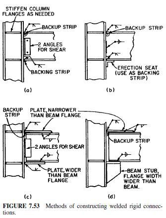


Welded Seat Connections Civil Engineering
A fin plate connection consists of a length of plate welded in the workshop to the supporting member, to which the supported beam web is bolted on site, as shown in the figure below There is a small clearance between the end of the supported beam and the supporting column · End Plate Steel Beam Connection This type of connection is made possible through the use of welding art The end plate is connected to the beam web through weld because its capacity and size is governed by shear capacity of the beam web adjoining the weld The load applied on the connection at the end of the member does not have eccentricitiesB Beam – Column Connections When a beam is to be connected to a column the following types of connections can be provided 1 When the Connection does not Provide Restraint against Rotation (a) Direct Web Fillet Welded Connection In this case the beam transmits its end reaction to the column entirely by shear


Performance Evaluation Tests Of Welds And Beam To Column Connection Welds Jfe Techno Research Corporation
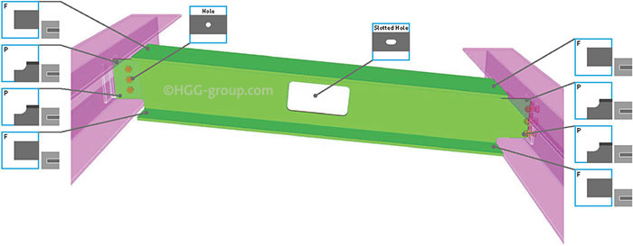


The 7 Most Used Beam Connections Explained Hgg 3d Profiling
· I have designed flange plated connections where we weld a deck support plate to the underside of the bolted flange plate or butt welded to the beam flange Nothing big 1/4" thick with at least 3" of overhang to give deck bearing and a place to attach down toBoltedWelded Beam End Connection Using Single Clip Angle per AISC 13th Edition (ASD) Analysis and design of 4 and 8 tension bolt moment connections (per AISC 9th Edition ASD Manual) Calculates moment connection using flange plates (not end plates) AISC LRFD Shear Plate bolted connection check · CONNECTIONS IN STEEL STRUCTURES 2 Connections are structural elements used for joining different members of a structural steel frame work Steel Structure is an assemblage of different member such as "BEAMS,COLUMNS" which are connected to one other, usually at member ends fastners,so that it shows a single composite unit 3 Bolts Weld
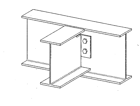


Beam To Beam Welded Joint Structural Engineering General Discussion Eng Tips
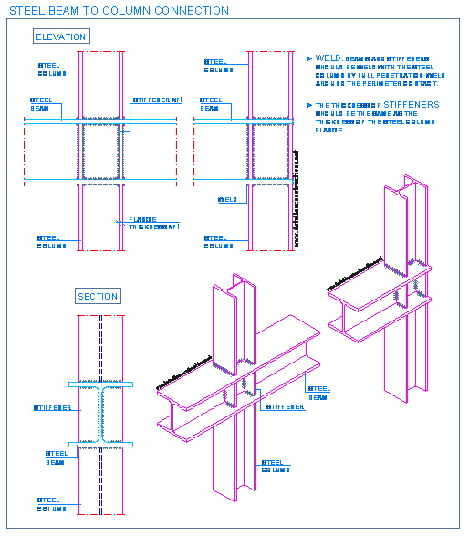


Steel Connections Detallesconstructivos Net
Lap Joint single riveted and double riveted When a beam is connected to the flange (or the web) of a steel stanchion, the width of theWelded beamtocolumn connections can be prepared in the fabrication workshop with a bolted splice connection within the beam spam, at a position of lower bending moment Welded connections are also used for the construction of buildings in seismic areas Other types of moment resisting connections includeWelded beam end connections shall be designed in accordance with the assumptions about the degree of restraint involved in the designated type of construction 28 Ecc entricity In the design of welded joints, the total stresses, including those due to eccentricity, if any,


Moment Connection 181 Tekla User Assistance
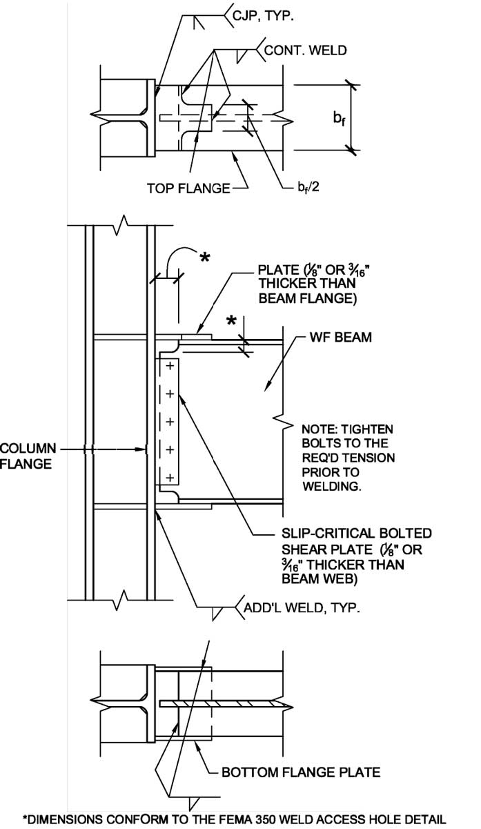


Structure Magazine Unanticipated Stresses And The Welded Flange Plate Moment Connection
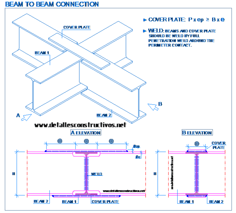
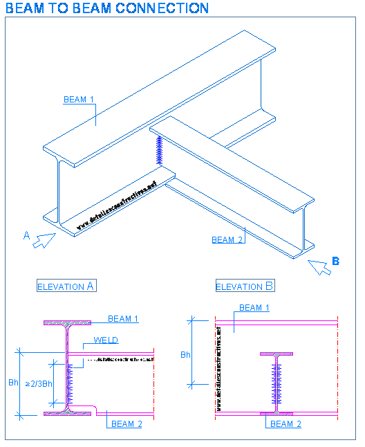
However, in beam structures welding is not so common (still I once did a project for a roof where literally all connections were welded) When it comes to stiffness I would say that prestressed connection that is reasonably designed is as rigid as welding (or at least reasonably close to it)0929 · Welded Splice Details For Steel Beams Posted on September 29, by Sandra Typical steel connections axial restraint in steel beams beam to column connection with end splicing i beams structural esdep lecture note wg11 Splicing I BeamsBeam to beam (same section) welded moment connection (one horizontal and the other inclined, ascending or descending) Beam to beam welded simple connection Beam to two beam welded simple connection Splice connection of continuous equal sections with plate Tie detail Baseplate on pad footings, pile caps and mat foundations
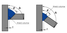


Hgg Group Stronger Welded H Beam Connections Read About Need To Know Welding Terms Useful For Weld Preparation For H Beams T Co Efqdq2jkxq T Co Grvupsrj8c


Concrete Column To Steel Beam Connection Hd Png Download Transparent Png Image Pngitem
Standard and most commonly used rigid beamcolumn connection withplate welded with end fillet welds at the end of the beam The modification used consists of additional triangular webs at the end of the beam that are welded to its upper and lower level with the endplate, so that the stiffnessin the end of the beam is enhanced 3 · I am working on a project involving welded beam to beam joints, please find the attached file for details It is a moment type joint, with full penetration weld connecting secondary beam flange to primary beam flange Corner radius in coping of 5mm referred in EN1090 for EXC2Welding our Incorrectly Cut IBeam Watch later Share Copy link Info Shopping Tap to unmute If playback doesn't begin shortly, try restarting your device Up Next


Why Do Structural Engineers Sometimes Choose To Bolt Steel Members And Sometimes Weld Them Together Quora
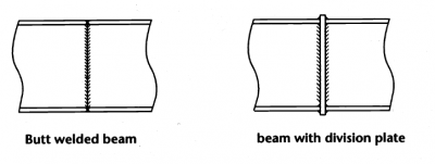


Moment Resisting Connections Steelconstruction Info
It's a pure AISC solution which can cover 90~95% of steel connections design in most projects, with specific strength on brace connection design including vertical brace, horizontal brace,chevron brace, knee brace, ver brace to base plate , and wrap around gusset plate design in horizontal brace2CHAPTER 6 WELDED CONNECTIONS 61 INTRODUCTORY CONCEPTS • Structural welding is a process by which the parts that are to be connected are heated and fused, with supplementary molten metal at the joint • A relatively small depth of material will become molten, and upon cooling, the structuralIDEA StatiCa Connection Verification example 1 Verification example – Welded beam to column moment connection Type of connection Welded beam to column moment connection Unit system Metric Designed acc to CSA S1416 Investigated Welds, base material, Plate Materials Steel grade 350W,


Wide Flange Beam To Hss Column Moment Connections Steel Tube Institute


Moment Connection Requires Bolts Outside The Flanges Ppt Video Online Download
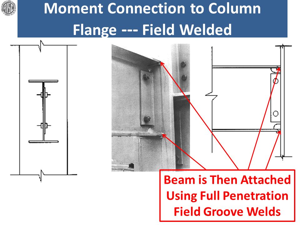
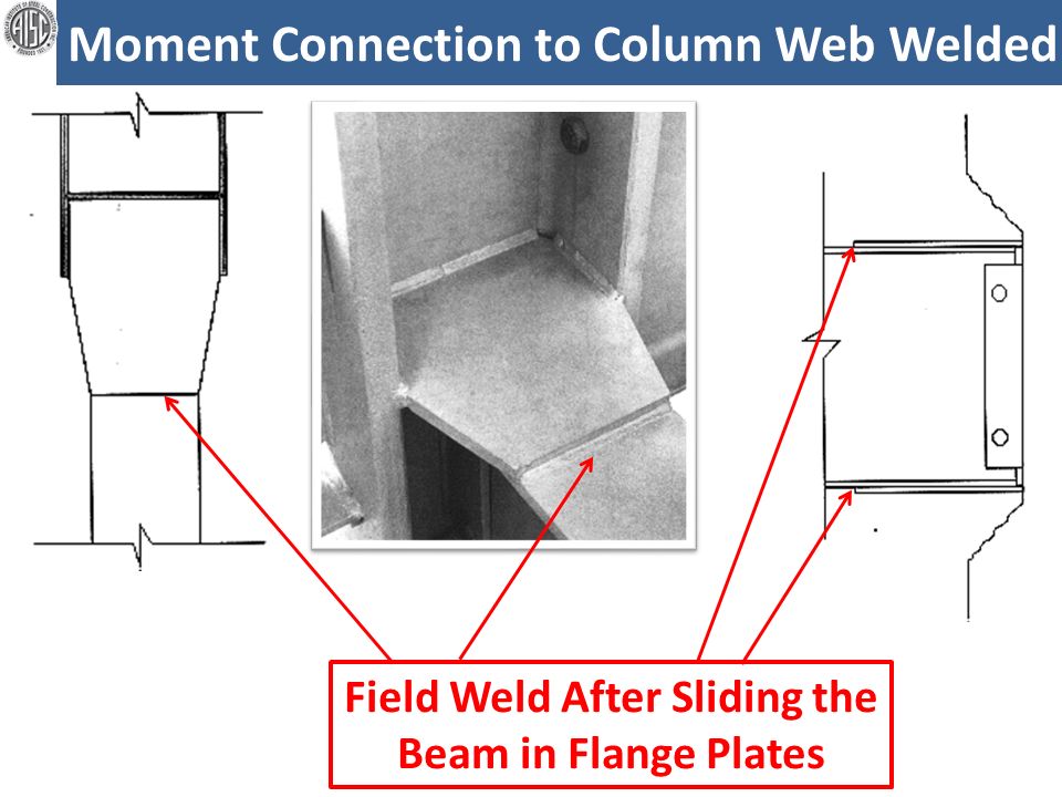
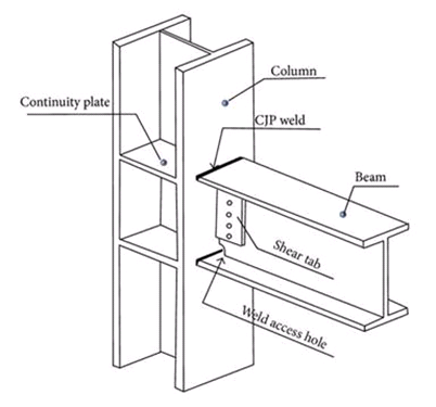
Connections of beams to columns Section 2 of the LRFD specification defines the following types of construction Type FR (fully restrained), directly welded flanged FR moment connections Both bolted and welded considerations will be covered for these connections 4This tutorial about weldment design in solidworks design hub provide detail tutorial about solidwork part design , solidworks weldments , solidworks structuWelded connections are widely used in beamtocolumn connection of steel frame as rigid connections But some diaphragms should be welded to the joints to obtain sufficient rigidity and strength, and it is observed in the recent earthquake damage, that the strain concentration in the vicinity of the weld may cause the fracture when loaded by severe earthquakes


How To Understand Staad There Is A Splice Connection With Welded Joint Ram Staad Forum Ram Staad Bentley Communities


Masterseries Masterseries 19 Sneak Preview Shop Welded Moment
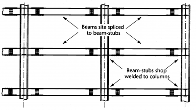
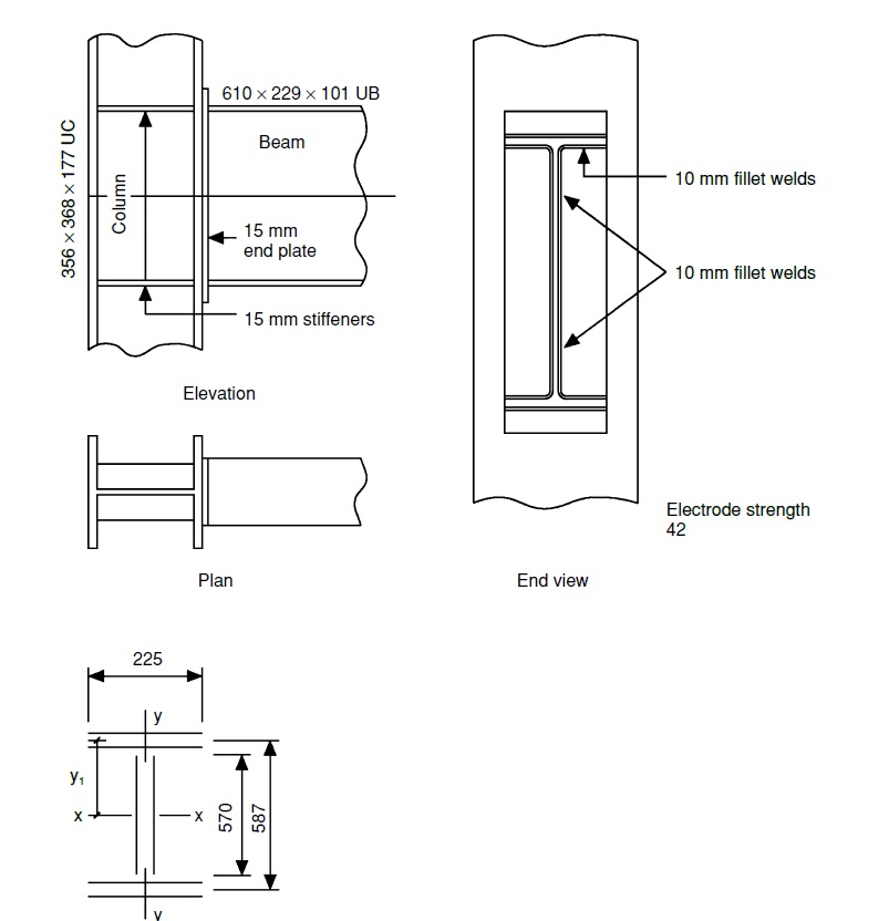
A welded beam to beam connection, fully fixed for high performance steel structures A welded beam to beam connection, pinned with snipe for supporting members in high performance steel structures See more examples in the article 'The 7 Most Used Beam Connections Explained'In momenttree connections, the 'stub' is shopwelded to the column and 'spliced' to accommodate the connecting beam This construction method reduces the demands on the connection by moving the 'hingepoint of the connection away from the column to the splice, significantly reducing the stress concentrations at the beam / flange weldThe connection is to be designed to transmit a bending moment of 500 kN m and a shear force of 300 kN Show that the proposed welding scheme for this connection is adequate Solution Leg length of weld, s = 10 mm Effective length of weld is Weld second moment of area, I xx, is Weld shear (moment) is where y = D/2 = 587/2 = 2935 mm


Beam To Column Connection With End Plate Engineering Manuals Fin Ec Online Help


Moment Connection Requires Bolts Outside The Flanges Ppt Video Online Download
Beam connections and simple end plate connections 2474 Stiffener Welds Except where the ends of stiffeners are welded to the flange, fillet welds joining transverse stiffeners to girder webs shall start or terminate not less than four times, nor more than six times, the thickness of the web from the web toe of the webtoflange weldsWarehouses with rolled and welded steel I sections allows CYPECAD, CYPE 3D and Integrated 3D structures of CYPECAD to carry out an automatic analysis and design of I section welded connections (including baseplates) displayed in the Types of implemented welded connections and for the codes indicated in the Implemented design codes for welded jointsThis connection can also be used for multiple stories In this configuration, the beam is continuous, but the column is "spliced" The beam web can be stiffened with plates or with split HSS sections to match the column section to provide a load path for the column axial loads Directly Welded


Refined Analysis Of Fatigue Crack Initiation Life Of Beam To Column Welded Connections Of Steel Frame Under Strong Earthquake


Structure Steel To Wood Home Building In Vancouver
72 ADVANTAGES OF WELDED CONNECTIONS The gross sectional area of the welded members is effective since the welding process does not involve drilling holes Welded structures are comparatively lighter than corresponding riveted structures A welded joint has a greater strength sometimes equal to the strength of the parent metal itself · Welded Connections Welded connections have the primary advantage of being simple in design, requiring fewer parts and material Welds however shrink, and this effect needs to be considered in the design particularly for large welds In addition, the inspection of welds is more difficult and hence costlier and more difficult to maintainSpacer – beam When projects are struggling for height, for instance in basements and lofts, it is often preferable to replace a deep beam with two smaller beams However, to ensure stability and resistance to buckling, these beams need to be bolted together, and this is where a spacer is used, and is usually welded to one of the beams
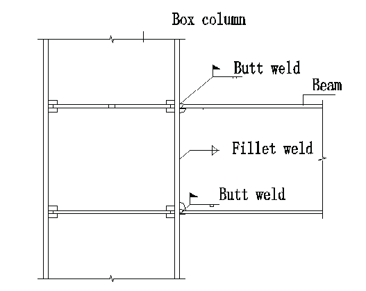


Beam To Column Connection Download Scientific Diagram


Beam Column Connection In Steel Moment Resisting Frame Piers Download Scientific Diagram
Beams used in the experimental study are IPE 0 with total length L t = 0 cm such that the length between supports is L= 180 cm Four vertical stiffeners at four point load (two bearing & two intermediate) were welded to the tested beams before loading The dimensions of tested beams and the test setup are shown in Fig 1
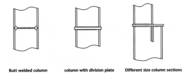


Moment Resisting Connections Steelconstruction Info
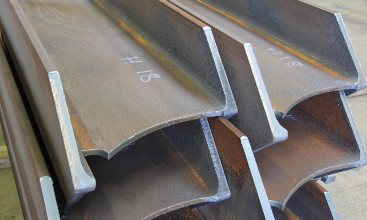


The 7 Most Used Beam Connections Explained Hgg 3d Profiling


Welded Joints Of Rolled And Welded Steel I Sections


Steel Connection Eliminates Field Welding Retrofit


The Welding Connection Between The Steel Beam A Chegg Com


Design Of Steel Connection 13ed


Beam To Beam Single Plate Connection
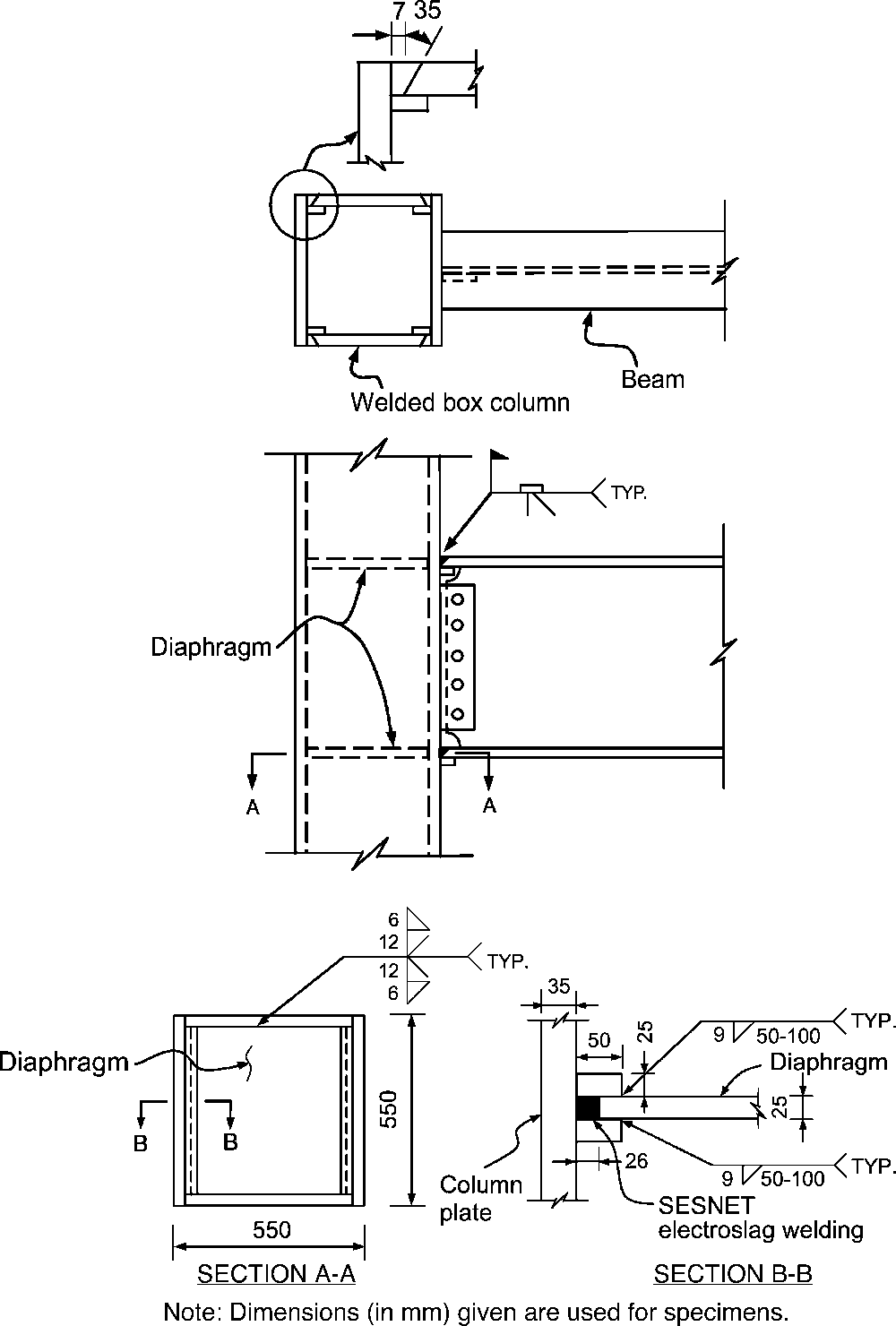


Figure 1 From Evaluation Of Reinforced Connections Between Steel Beams And Box Columns Semantic Scholar


1 Minute Steel Connection Design Welded Beam To Column To Beam With Stiffeners Youtube


Beams To Column Welded Connection 3d Warehouse
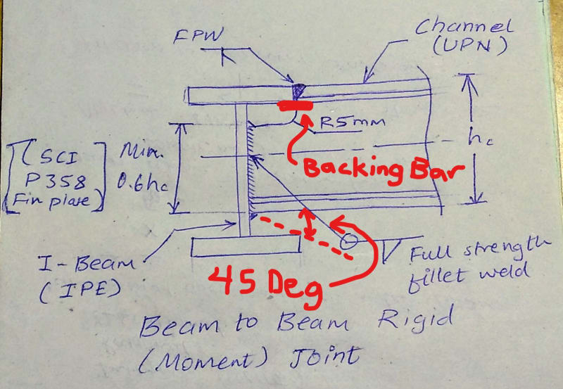


Beam To Beam Welded Joint Structural Engineering General Discussion Eng Tips
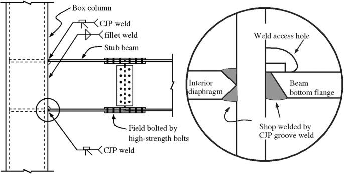


Study Of The Behavior Of Beam To Column Moment Connections With Tapered Beams Springerlink


Steel Beam Connections Construction Cost
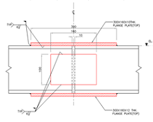


Weld Process And Joint Design And Engineering Formula Menu Engineers Edge


Beam To Column Web Welded Moment Connection Continuous Column In 21 Weld Beams In This Moment
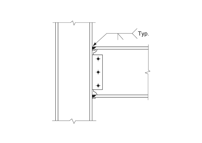


Engineers Corner Moment Connections Designed For The Plastic Moment Cisc Icca
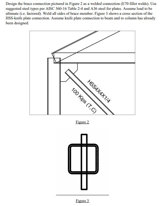


Solved Design The Brace Connection Pictured In Figure 2 A Chegg Com


Pin On Architecture


Types Of Steel Beam Connections And Their Details


How Can A Gusset Be Connected To A Main Beam Graitec


China Cheap Easy Assemble Building Material Welded Connection H Beam Poultry House Steel Structure China Steel Structure Warehouse Steel Frame Warehouse
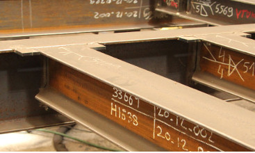


How To Make Strong Welded H Beam Connections Hgg 3d Profiling
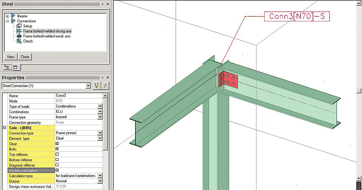


Sensd 10 Steel Connection Design And Drawings


Staad And Ram Connection For Direct Weld Steel Connection Youtube


Welded Connection An Overview Sciencedirect Topics
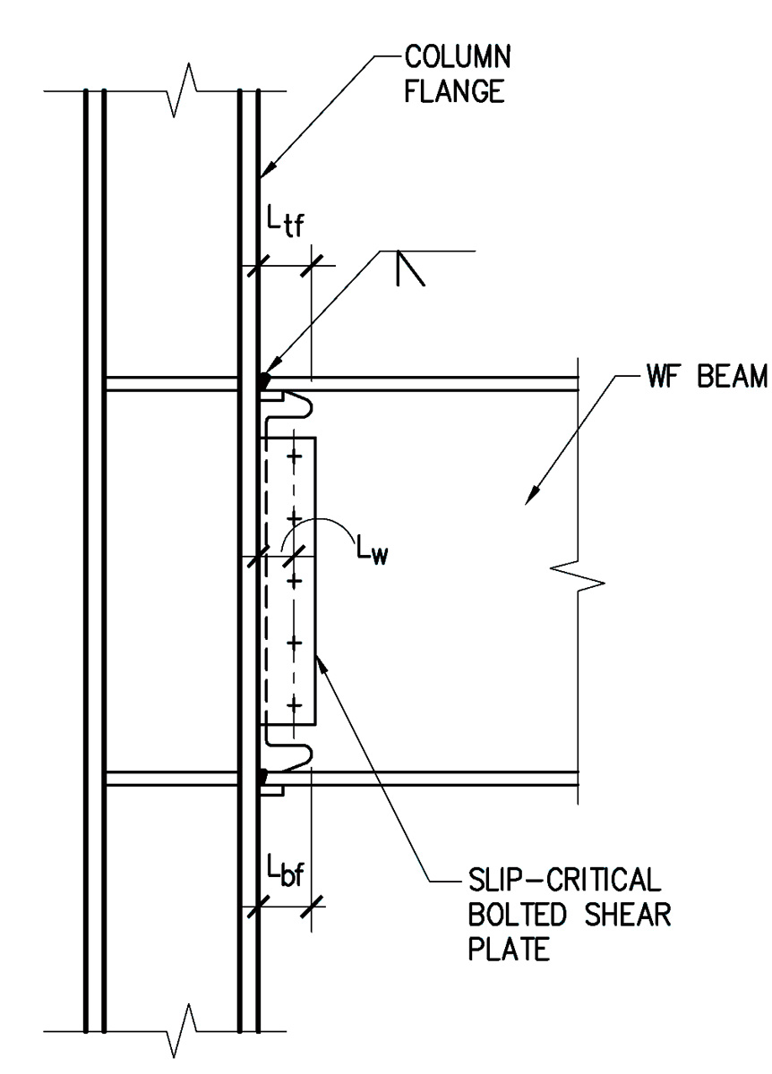


Structure Magazine Unanticipated Stresses And The Welded Flange Plate Moment Connection


Beam To Beam Endplate Steel Connection Detail


Structural Design Of Steel Fin Plate Connection Structville


Masterseries Masterseries 19 Sneak Preview Shop Welded Moment
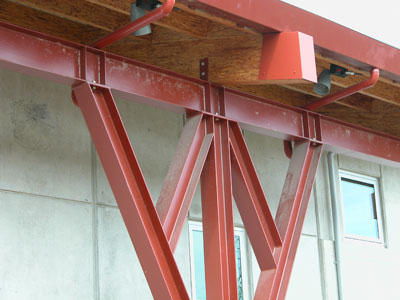


Ssef Fun Is In The Details Structural Shapes
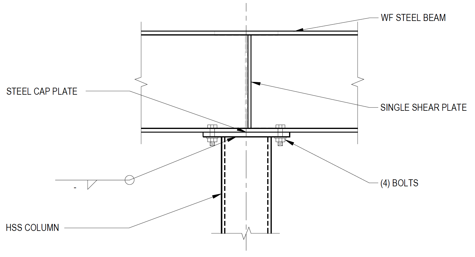


Wide Flange Beam To Hss Column Moment Connections Steel Tube Institute


Cft Beam To Column Directly Welded Connection 44 Download Scientific Diagram


Steel Connection Details Google Search Edificios Con Estructura De Acero Casas Con Estructura De Acero Edificios De Acero


Field Welded Moment Connection Download Scientific Diagram
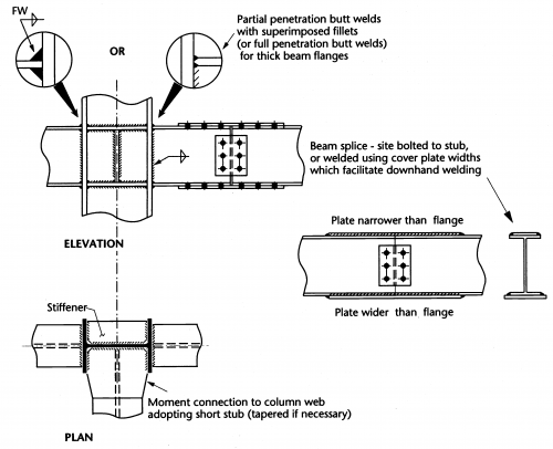


Moment Resisting Connections Steelconstruction Info


Steel Beam To Column Welded Connection Welding Construction
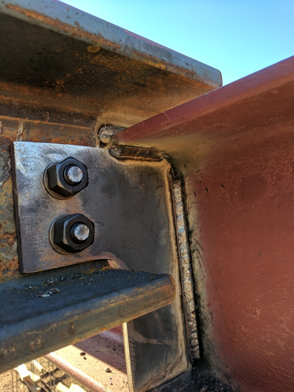


Field Retrofit Of Steel Beam Connection Structural Engineering General Discussion Eng Tips


Asi Design Guide 11 Welded Beam To Column Moment Connections


Welded Joints Of Rolled And Welded Steel I Sections


Solved Structural Connections Welded Connection Of Two Beams Autodesk Community Revit Products


Prediction Of Fracture Behavior Of Steel Beam To Column Connections With Weld Defect Using The Sintap Sciencedirect


Moment Resisting Connections Steelconstruction Info


Types Of Steel Beam Connections And Their Details


Types Of Steel Beam Connections And Their Details


Beam To Beam Welded Connection Hd Png Download Transparent Png Image Pngitem


Bolted Connection Plate Welded To A Metal Beam Natural Lighting Side View Close Up Stock Photo Alamy


Welded Joints Of Rolled And Welded Steel I Sections


Ram Connection 22 Smart Fp Beam Splice Welded Flange Plate Youtube


Detallesconstructivos Net Construction Details Cad Blocks


Externally Reinforced Welded I Beam To Box Column Seismic Connection Journal Of Engineering Mechanics Vol 136 No 1


How To Make Strong Welded H Beam Connections Hgg 3d Profiling


Scielo Brasil Seismic Performance Of Post Northridge Welded Connections Seismic Performance Of Post Northridge Welded Connections


Solved Example Analysis Of A Welded Steel Beam To Column Connection Bs 5950 Civilengineeringbible Com


Construction Concerns Welded Connections Fire Engineering


Pdf Evaluation Of Welded Flange Plate Connections Between Steel Beams And Box Columns Semantic Scholar


Factory Supply Cheap Fabricated Weld Steel I Beam With Cleat Connection Buy Fabricated Weld Steel I Beam Largest I Beam Steel I Beams For Sale Product On Alibaba Com


Welded Joints Detallesconstructivos Net


Structure Steel To Wood Home Building In Vancouver


How To Design A Shear Connection Skyciv Cloud Structural Analysis Software


Solved Structural Connections Welded Connection Of Two Beams Autodesk Community Revit Products


Welded Connection Beam Joints Welded 843x590 Png Download Pngkit


Types Of Steel Beam Connections And Their Details


Steel Connections Moment End Plate Graitec


Steel Connections Detallesconstructivos Net


The Earthquake Safety Of Pre Northridge Welded Steel Moment Frame Buildings Air Worldwide
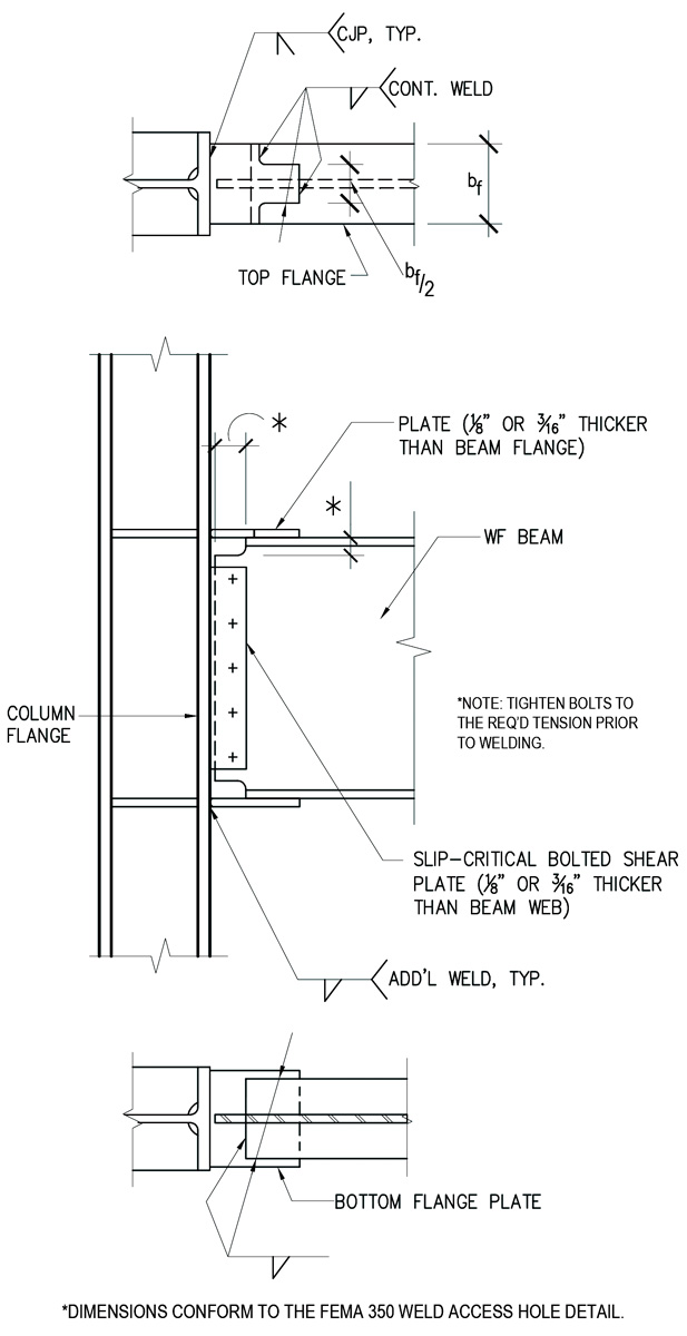


Structure Magazine Unanticipated Stresses And The Welded Flange Plate Moment Connection


Fragility Functions For Pre Northridge Welded Steel Moment Resisting Beam To Column Connections Sciencedirect


Steel Connections Software Cse Tour Beam To Beam Welded Joint Youtube


Pin On Hill House


How To Create A Sloping Beam Welded To A Column Revit Forum
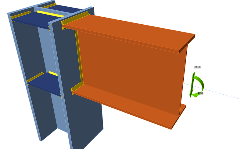


Welded Portal Frame Eaves Moment Connection Idea Statica


7 Types Of Connections That Can Be Easily Design With Steel Connection Designer Civil Engineering Software Solutions


Steel Beam Reduced Size Welded Splice Connection Detail Structuraldetails Store
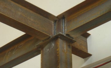


Steel Building Structure Connection Metal Structure Havit Steel


Welded Joints Of Rolled And Welded Steel I Sections
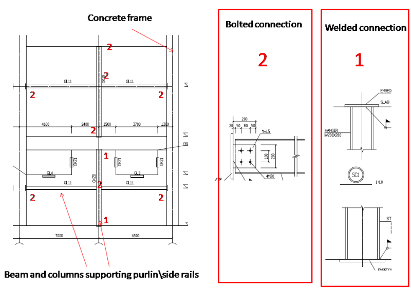


Welded Connections To Concrete Frame Structural Engineering General Discussion Eng Tips


Detail Of Beam Connection Simple Framing Connection Semi Rigid Framing Connection Rigid Frame Connection


0 件のコメント:
コメントを投稿